mechanical subsystem

Mechanical subsystem.
|
|
INTRODUCTION
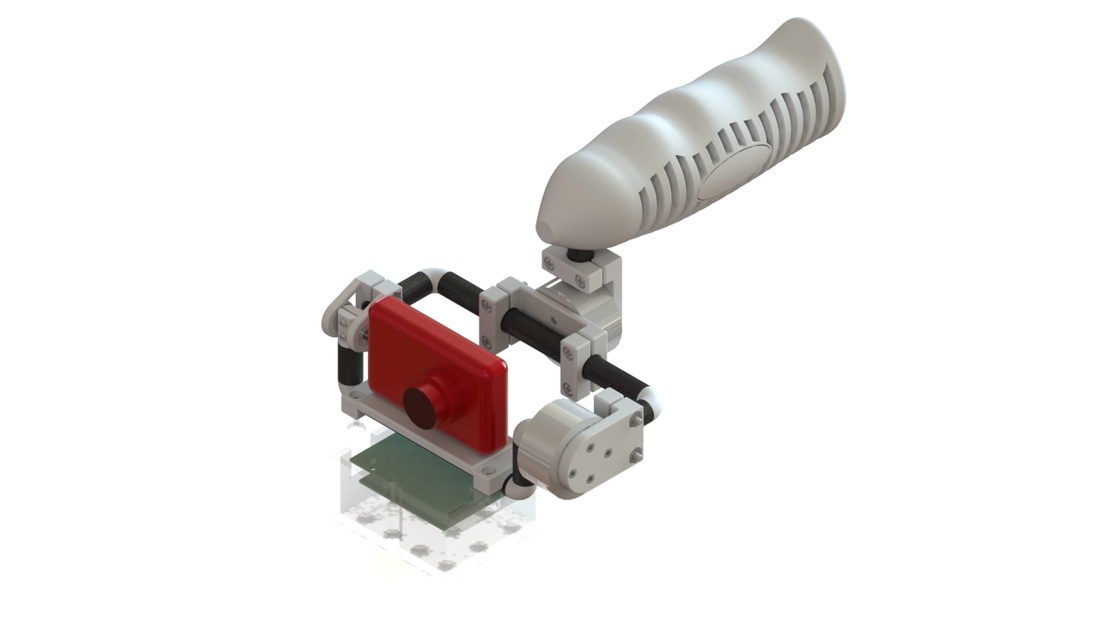
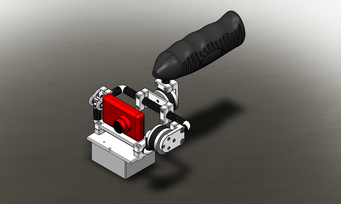
The mechanical subsystem consists of the structure, the camera, and the motors. The structure has four major areas: the frame, the PCB mounts, the camera mount, and the motor mounts. The frame is subdivided into the carbon fiber tubing and the 3-D printed clamps.
The mechanical subsystem consists of the structure, the camera, and the motors. The structure has four major areas: the frame, the PCB mounts, the camera mount, and the motor mounts. The frame is subdivided into the carbon fiber tubing and the 3-D printed clamps.
|
THE STRUCTURE
Since the structure provides the skeleton for the entire system, it needs to adhere to all six major requirements for the system, reiterated below:
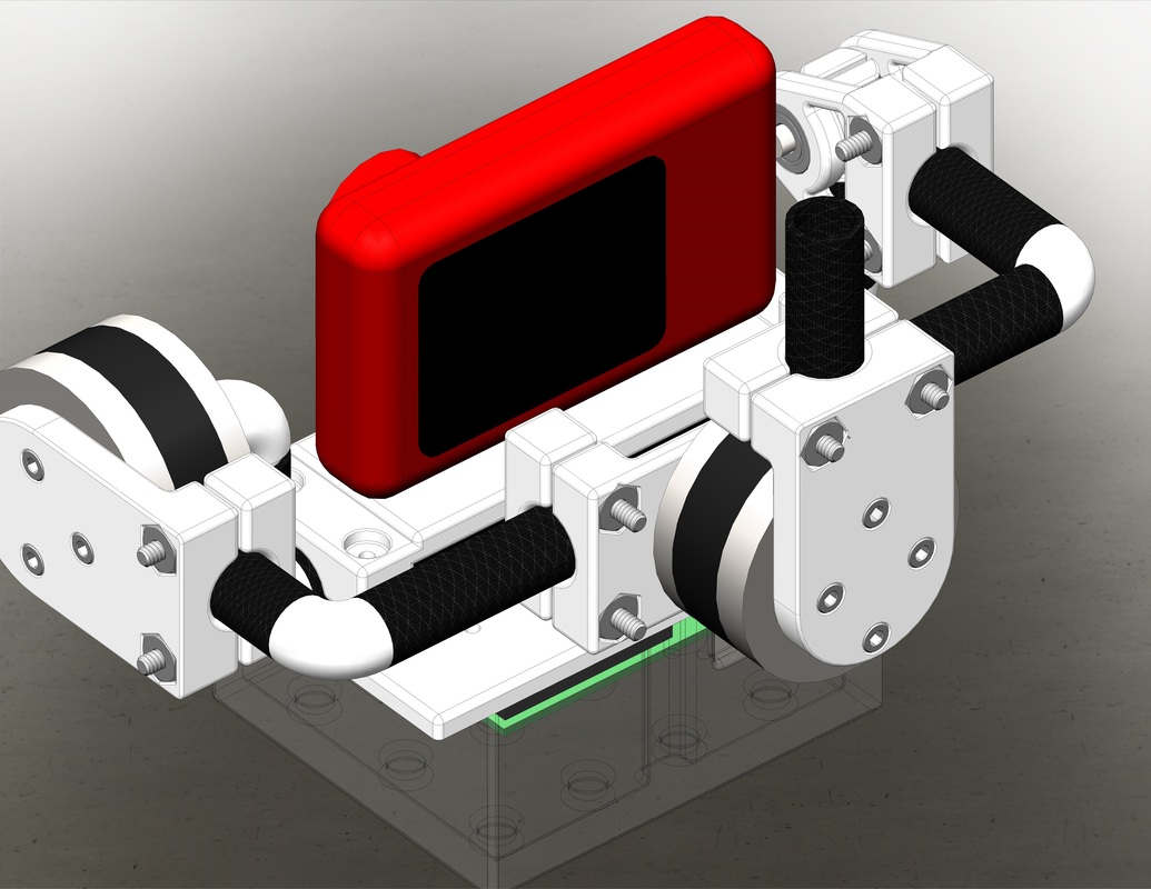
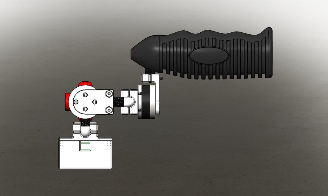
THE FRAME The overall frame must be made out of lightweight materials since the entire system is aimed at being 1-2 lbs. It must also be strong enough to support a camera, two motors, a LiPo battery, and accompanying electronics. The frame materials and geometry must also be resistant to excessive vibration when when the motors move the entire frame to adjust for the camera so the video quality is not shaky. While we could have used sheet metal, delrin, or PVC pipes for the frame, we decided that the most aesthetically pleasing and highest strength to weight ratio was carbon fiber tubing. The frame also needs to be able to move in the roll and tilt axes. When the roll motor moves, the entire frame moves. When the tilt motor moves, only a portion of the structure moves. This allows the motors to correct for both roll and tilt. |

|
|
The clamps are customized for the 1/2" carbon fiber tubes. They are used to connect separate parts of the frame and are comprised of two pieces. They are 3-D printed for ease of customization and are held together with #6-32 screws and nuts. The clamps are also designed with a counter bore for the head of the screw and the entire nut so that the nut does not move relative to the screw when being torqued during assembly. This ensures a strong clamping force.
|

|
|
The elbows are also 3-D printed because we were unable to find standard PVC elbows that mated snugly with the carbon fiber tubing. While the elbows have a slight press/interference fit with the carbon fiber tubes, we ensure a solid connection between the two with the aid of epoxy. Carbon fiber and ABS plastic react to epoxy well, and this provides an extremely strong connection.
|

|
|
THE CAMERA MOUNT
The camera mount is attached to the PCB mount and keeps the camera and PCB parallel since the orientation data for the motors comes from the PCB. The camera mount also attached to the frame such that it can center the camera through the center of the roll motor. The camera mount is designed to be in the center of the tilt motor. THE PCB MOUNT The PCB mount is attached to the camera mount to keep the PCB and camera parallel. The PCB mount protects the PCB as well. |


|
|
THE MOTOR MOUNTS
The handle is designed to house the battery and be held with one hand, similar to how one would hold a camcorder. It is designed in two parts so that the battery can be put in, and it is held together by two spring pin dowels. The handle also has a hole from the battery cavity to the mating hole for the rest of the frame. The battery holder also allows the battery cables to be wired through to the motors. |
|
|
HANDLE/BATTERY HOLDER
The handle is designed to house the battery and be held with one hand, similar to how one would hold a camcorder. It is designed in two parts so that the battery can be put in, and it is held together by two spring pin dowels. The handle also has a hole from the battery cavity to the mating hole for the rest of the frame. The battery holder also allows the battery cables to be wired through to the motors. 
|
|
Build and Assembly
The following is a list of parts that were fabricated with the 3-D printer:
While the majority of the parts were designed to not need much post-machining, the holes on the most of the 3-D printed parts either needed to be enlarged or tapped, and this took a few hours to complete. The general assembly of the entire system went fairly smoothly, and there is not much interference or friction within the system. This allows for the system to compensate without too much vibration. There is some residual interference on the side with the shaft and bearings for the tilt axis, and when the system actually tries to compensate too much in this direction, the system is a little jittery.
The following is a list of parts that were fabricated with the 3-D printer:
- handle
- clamps
- camera mount
- motor mounts
- PCB box
While the majority of the parts were designed to not need much post-machining, the holes on the most of the 3-D printed parts either needed to be enlarged or tapped, and this took a few hours to complete. The general assembly of the entire system went fairly smoothly, and there is not much interference or friction within the system. This allows for the system to compensate without too much vibration. There is some residual interference on the side with the shaft and bearings for the tilt axis, and when the system actually tries to compensate too much in this direction, the system is a little jittery.
